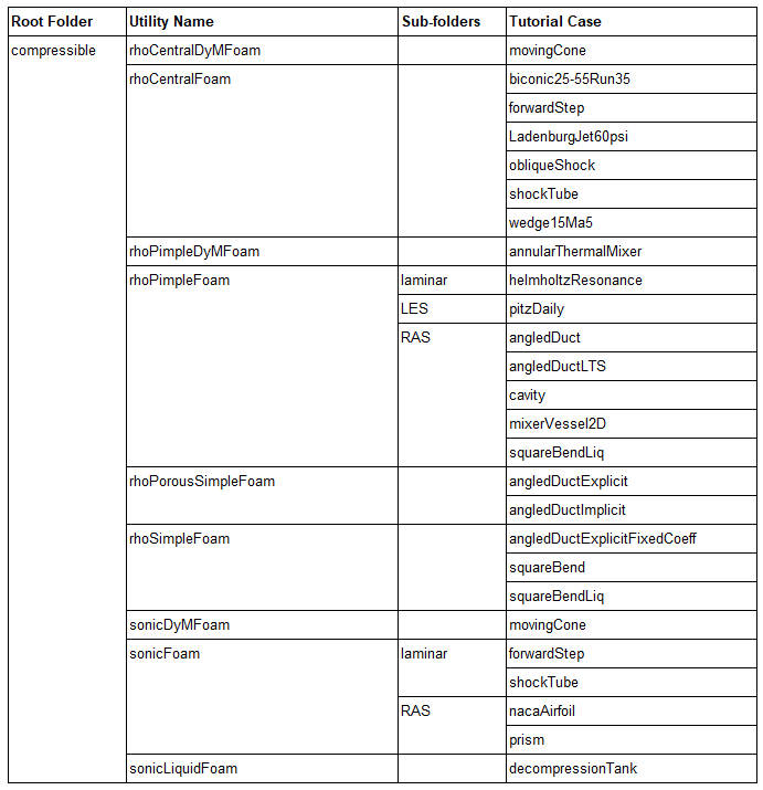
- Summary of OpenFOAM Tutorials
CFD Simulations in OpenFOAM
Open-source CFD toolbox: OpenFOAM is now a mature open-source CFD program with reliability matching that of commercial products. This page describes summary of utilities and dictionaries used in OpenFOAM meshing and visualization such as (blockMesh, snappyHexMesh, ParaView) and OpenFOAM CFD codes and pre-processors such as (simpleFoam, pimpleFoam, engineFoam...).
OpenFOAM CFD: A Beginner's Diary
Disclaimer:
This content is not approved or endorsed by OpenCFD Limited, the producer of the OpenFOAM CFD software and owner of the OpenFOAM and OpenCFD trademarks.Table of Contents
incompressible/simpleFoam/pitzDaily [-] Flow around Buildings - snappyHexMesh (+) Rotating Walls and Domains {+} pimpleDyMFoam - Moving Cone {=} Multi Region Heater - Conjugate Heat Transfer (=) Adjoint Solvers [=] Electromagnetics {*} List of Sampe Cases (*) snappyHexMeshOpenFOAM Tutorials Catalogue
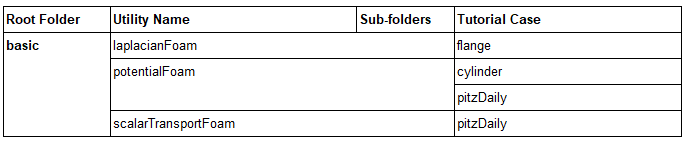
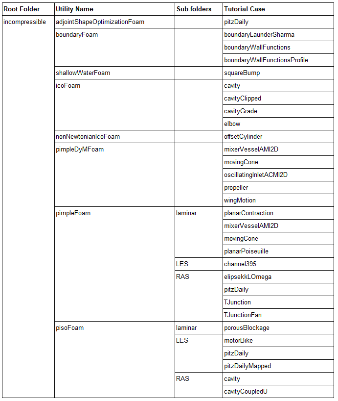
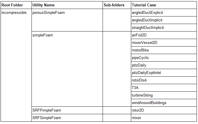
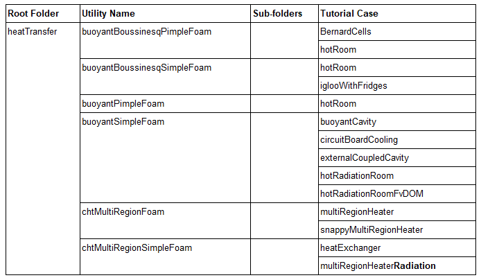
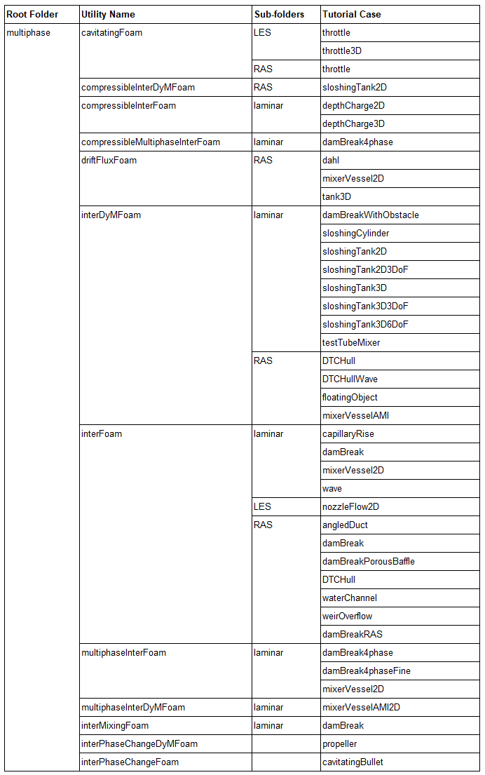
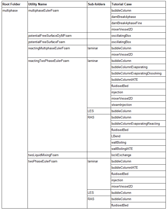
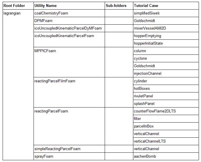
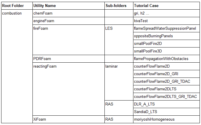
This page summarizes the cases - especially geometry and flow physics available as test cases in OpenFOAM tutorials folder. This is an attempt to sort of create a catalogue so that any new user can choose which module or application of openFOAM to start with. Sometimes even experience CFD practitioner not familiar with openFOAM may have a "sinking in ocean" feeling like I had! The purpose is to have this visual catalogue and nothing else! This content is prepared as recorded by a new learner (during his ongoing journey to become an OpenFOAM expert) with anticipation that it will be helpful to others as well.Test Cases in Official Release Tutorial - There are 5 different cases explained in an excellent way the simulations process to be followed in OpenFOAM. An equally impressive set of tutorials for 11 additional cases can be found here.
For users starting to program own solver, this article will of great help!
Combustion Modeling - XiFoam tutorial available from
http://www.tfd.chalmers.se/~hani/kurser/OS_CFD_2010/ehsanYasari/ehsanYasariReport.pdf
Combustion Modeling - reactingFoam
The cases demonstrating incompressible, steady state flow based in SIMPLE algorithm are airFoil2D, mixerVessel2D, motorBike, pipeCyclic, pitzDaily, pitzDailyExptInlet, rotorDisk, simpleCar, turbineSiting, windAroundBuildings. They are pictorially described below. All of the case folders have a file named "Allrun". This contains the sequence of operation required to be run. For example, the case "turbineSiting" contains following set of instructions in Allrun file:
    runApplication blockMesh
    \cp system/decomposeParDict.hierarchical system/decomposeParDict
    runApplication decomposePar
    \cp system/decomposeParDict.ptscotch system/decomposeParDict
    runParallel snappyHexMesh -overwrite
    find . -type f -iname "*level*" -exec rm {} \;
    # - set the initial fields
    restore0Dir -processor
    runParallel topoSet
    runParallel $(getApplication)
    runApplication reconstructParMesh -constant
    runApplication reconstructPar
However, if one does not want to run parallel version (using more than 1 processor), simply use blockMesh and then snappyHexMesh on the command prompt to get the desired mesh, thus skipping the utilities decomposePar, reconstructParMesh and reconstructPar. List of Sampe Cases
The properties of fluid defied in constant/thermophysicalProperties:
thermoType hThermo<pureMixture<constTransport<specieThermo<hConstThermo<perfectGas>>>>>;The meaning of each term is as follows:
- perfectGas: Perfect gas equation of state.
- hConstThermo: Constant specific heat Cp model with evaluation of enthalpy h and entropy s.
- specieThermo: Thermophysical properties of species, derived from Cp, h and s.
- constTransport: Constant transport properties.
- ureMixture: General thermophysical model calculation for passive gas mixtures.
- hThermo: General thermophysical model calculation based on enthalpy h.
boundaryFoam
As per user guide: "Steady-state solver for incompressible, 1D turbulent flow, typically to generate boundary layer conditions at an inlet". The description of flow geometry and boundary conditions used are shown below.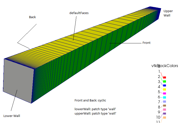
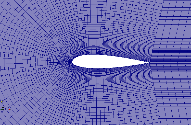
incompressible/simpleFoam/airfoil2D A detailed description of this tutorial case by Grant Ingram from Durham University can be found here.

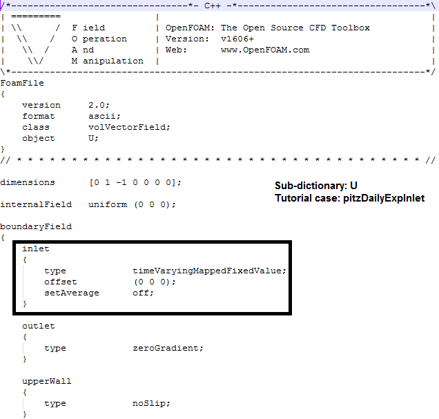
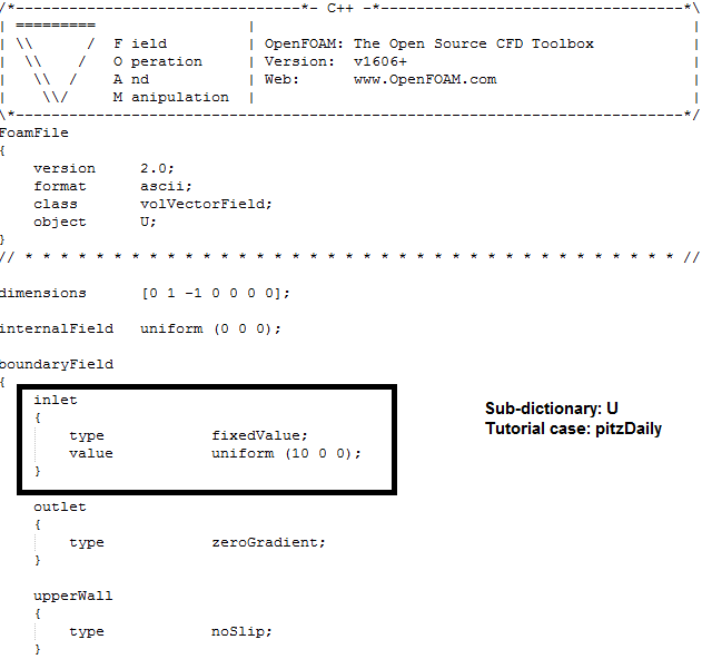
incompressible/simpleFoam/pitzDaily
This is one of the test cases described in user guide. There are two simulation cases - they differ mainly between the turbulence model used and the way input boundary conditions are specified. "pitzDailyExptInlet" demonstrate how to interpolate or apply non-uniform boundary conditions at the inlet. The differences in U sub-dictionaries are shown below.
Go to top
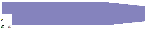
incompressible/simpleFoam/simpleCar This is a good demonstration of block mesh utility to generate mesh with internal cavities and nice representation of car as simplified geometry.
Incompressible/simpleFoam/pipeCyclic This demo case shows how to use parameter definition in blockMeshDict, use of #calc utility and create wedge elements [axisymmetric domain with zero inner radius]. The blockMesh utility creates on-the-fly library for few occurrence of #calc [in Windows version of 1606+]. Some messages appearing in the terminal are:
  wmakeLnInclude: linking include files to ./lnInclude
  ln: creating symbolic link './codeStreamTemplate.C': Protocol error
  Making dependency list for source file codeStreamTemplate.C
  Creating new library in "dynamicCode/_9273df81ebe52476e105ce9128b702a57ad95417/platforms/
  linux64GccDPInt32Opt/lib/libcodeStream_9273df81ebe52476e105ce9128b702a57ad95417.so"
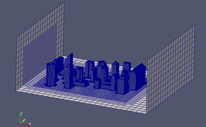
Flow around Buildings - snappyHexMesh
This case demonstrates snappyHexMesh utility. User should follow the steps defined in file Allrun. The Utility surfaceFeatureExtract (surfaceFeatures from V8 onwards) needs to be run before snappyHexMesh. 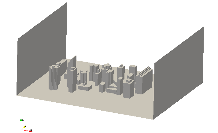
Reading surface from "constant/triSurface/Fan_in_Duct.stl" ...

Statistics:
Triangles    : 23474
Vertices     : 11749
Bounding Box : (-550 -185 -185) (540 185 185)

Region  Size
------  ----
patch0  23474

Surface has no illegal triangles.

Triangle quality (equilateral=1, collapsed=0):
    0.00 .. 0.05  : 0.1744
    0.05 .. 0.10  : 0.1612
    ...

    min 4.76e-06 for triangle 19519
    max 0.999899 for triangle 11050

Edges:
    min 0.00290 for edge 352 points (-22.92 108.37 143.69)(-22.9 108.37 143.7)
    max 500.073 for edge 101 points (-550.0 152.62 104.55)(-50.0 157.29 97.39)

Checking for points less than 1e-6 of bounding box ((1090 370 370) metre) apart.
Found 0 nearby points.

Surface is not closed since not all edges connected to two faces:
    connected to one face : 24
    connected to >2 faces : 8
Conflicting face labels:48
Dumping conflicting face labels to "problemFaces"
Paste this into the input for surfaceSubset

Number of unconnected parts : 2
Splitting surface into parts ...

Writing zoning to "zone_Fan_in_Duct.vtk"...

writing part 0 size 1084 to "Fan_in_Duct_0.obj"
writing part 1 size 2239 to "Fan_in_Duct_1.obj"

Number of zones (connected area with consistent normal) : 10
More than one normal orientation.
The command surfaceFeatureExtract creates the *.eMesh files from the *.stl files with the geometry data. Folder extendedFeatureEdgeMesh is created in the constant directory. The creation of eMesh files with the command surfaceFeatureExtract is not mandatory stops to use sHM. This step isnecessary only if edges need to be refined.
Rotating Walls and Domains
mixerVessel2D - simpleFoam This case can be obtained by adding baffles to the case 2D rotor. However, note that 2D rotor case uses simpleFoam and not SRFSimpleFoam. 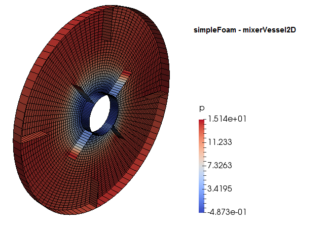
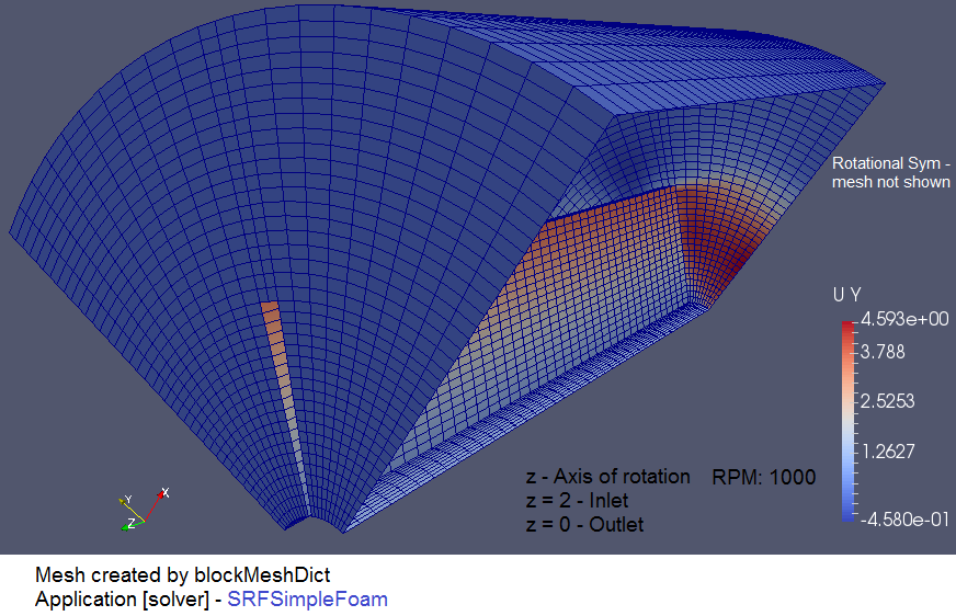
SRFSimpleFoam - mixer
Go to top
SRFPimpleFoam - 2D Rotor
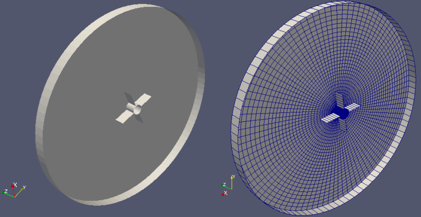
Go to top
pimpleDyMFoam - Moving Cone
In recent versions (OpenFOAM v1806 or later) the dynamic mesh functionality in pimpleDyMFoam has been merged into pimpleFoam and the pimpleDyMFoam tutorials moved into the pimpleFoam tutorials directory. This tutorial demonstrates the moving mesh without any re-meshing or addition/deletion of layer. The size of elements expands and contracts during the mesh motion with constant velocity 1 [m/s] defined in dictionary 0/pointMotionUx.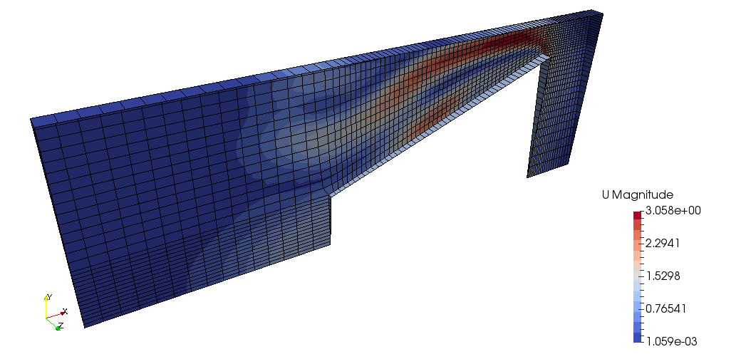
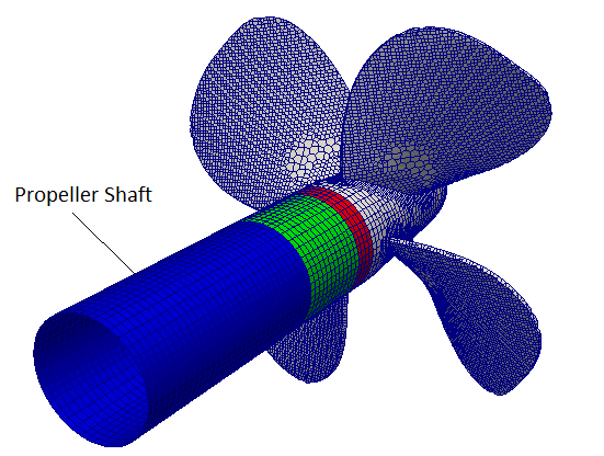
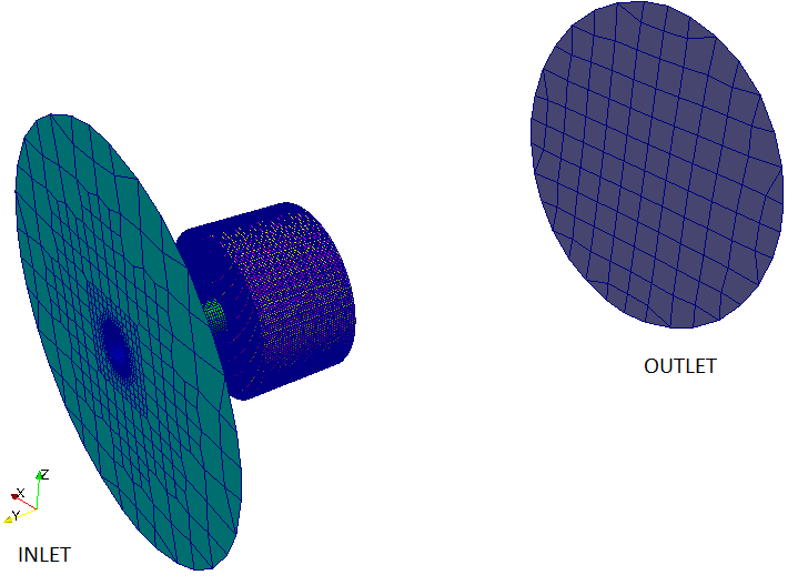
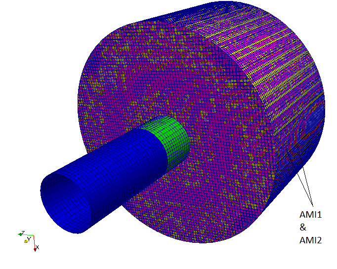
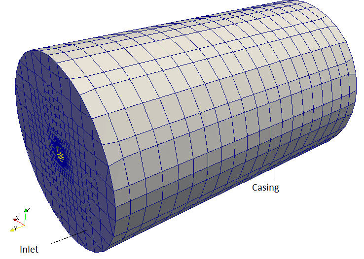
Go to top pimpleDyMFoam - propeller with AMI (Arbitrary Mesh Interface)
snappyHexMesh [sHM]
This utility is used to create high quality hex-dominant [cut-cell] meshes [similar to but not exactly Cartesian Mesh in ICEM CFD] based on arbitrary geometry, the controlling dictionary is system/snappyHexMeshDict. Requires a starting [hexahedral] mesh created by blockMesh [designated as base mesh or level 0 mesh] and geometry data in STL and Nastran (.nas) files format.A snappyHexMeshDict file created after reading through such files used in various tutorial application can be found here. This is a generic dictionary which demonstrates all the features of this utility.
Different stages of mesh generation in snappyHexMesh utility is shown in following images.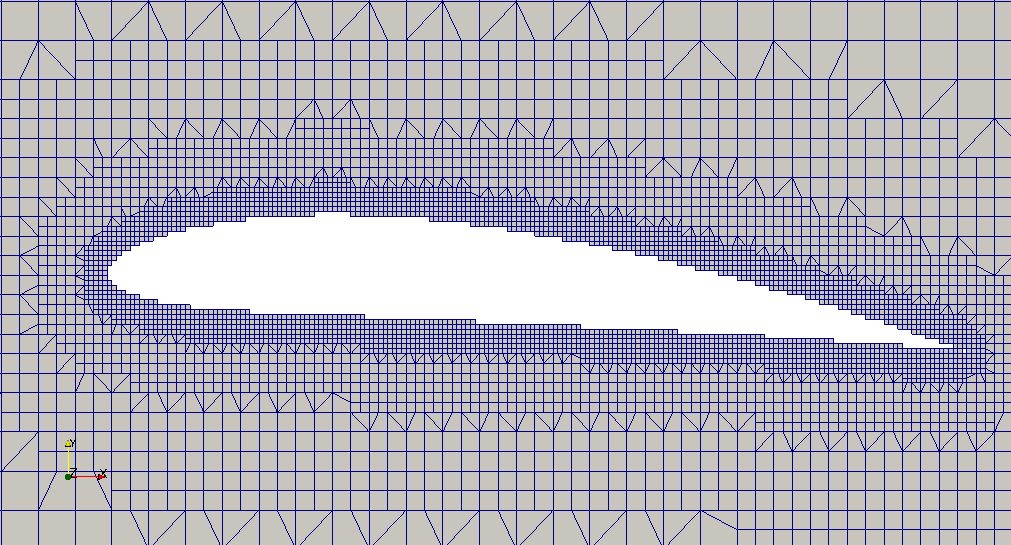
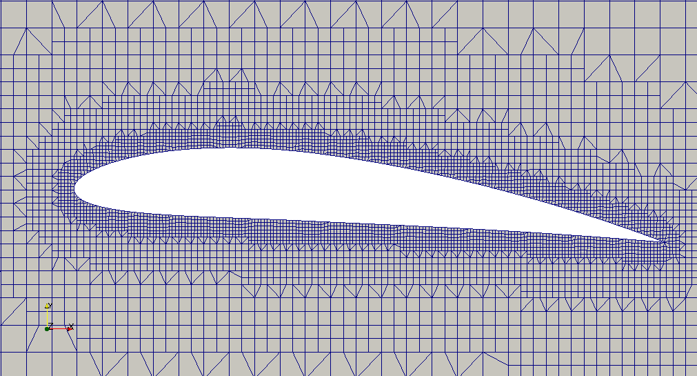
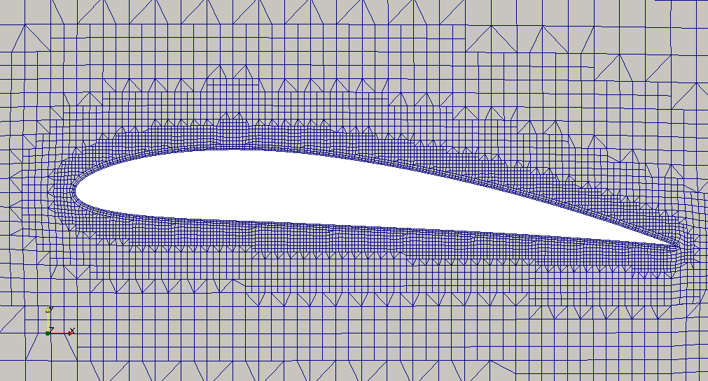
Note - By default, each phases of snappyHexMesh i.e castellation, snapping and layer addition will write a complete mesh in time folders. This behaviour can be suppressed by using the option -overwrite: "snappyHexMesh -overwrite"
Examples of snappyHexMesh application can be found in tutorial cases:- incompressible/windSimpleFoam/turbineSiting
- incompressible/simpleFoam/turbineSiting
- incompressible/pisoFoam/les/motorBike/motorBike
Steps for snappyHexMesh (sHM) when a CAD data is available in STEP format.
Step-1: Convert to STL - sHM reads CAD geometry that is boundary of computational domain in STL format. This can be accomplished by importing the geometry into FreeCAD and then using File -> Export utility to save the geometry as STL file. Even latest versions of STAR-CCM+ and FLUENT Mesher converts the CAD into faceted (STL) form before meshing operations can be performed. Make sure that the model is in [m] as OpenFOAM operates on [m] as default unit.
Step-2: check the dimensions of a bounding box - this is required to create a bounding box for background mesh encompassing entire STL geometry. Use surfaceCheck utility as described in ealier section.
Step-3: Update the dimensions of bounding box in blokcMeshDict - reference dictionary can be found here. Geneate blockMesh and open it along with STL file in ParaView to ensure the blockMesh covers the STL geometry.
Step-4: Extract edges of from STL geometry - use surfaceFeatures [surfaceFeatureExtract is obsolte in V8] to create feature edges such sharp corners, intersections... This will create a geomData.eMesh file in the folder where geomData.stl file is located.
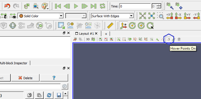
Step-5: Estimate a point inside the computational domain in the CAD environment - This is required to tell sHM which region of mesh to be retained - inside STL geometry or outside it. Use "Hover Points On" feature in ParaView to get approximate coordinates.
Step-6: Update snappyHexMeshDict - update the name of STL file in this dictionary, specify a material point in the fluid region (domain to be meshed), create BOdy-of-Influence (BOI), define patches.
Step-7: Create patches using topoSet utility - update the topoSetDict to create patches from cell faces. This is required to specify boundary conditions. You may need to use "Hover Points On" feature in ParaView to get approximate bounding box of the patches.
- The background mesh must contain only hexahedrons.
- The cell aspect ratio should be approximately 1, at least near the STL surface.
- There should be at least 1 intersection of a cell edge with the STL surface.
- The STL geometry can be obtained from any 3D CAD geometry modeling tool or pre-processor so long it results in a water tight geometry.
- The STL file can be made up of a single surface describing the geometry or multiple surfaces that describe the geometry.
- In the case of a STL file with multiple surfaces, local refinement in each individual surface can be exploited.
- Multiple STL files can be used.
- The STL geometry is always located in the directory constant/triSurface.
- The final mesh is always placed in the directory constant/polyMesh.
Error in topoSet utility: "Cannot find directory "polyMesh/sets" in times "0" down to constant" - this error occurs when topoSet cannot find the faceSet or cellSet. Check for entry "action new;" in topoSetDict. Additional Check - Note size of faceSet outletFaces is '0' which implies the box specified is not correct and does not encompass any cell.
Created faceSet inletFaces
    Applying source boxToFace
    Adding faces with centre within boxes 1((-0.02 -0.02 -0.025) (0.02 0.02 -0.0195))
    faceSet inletFaces now size 2272
Created faceSet outletFaces
    Applying source boxToFace
    Adding faces with centre within boxes 1((0.11 -0.025 -0.025) (0.09905 0.025 0.025))
    faceSet outletFaces now size 0
Errors in createPatch: Use -overwrite option to avoid creation of a new time directory.
Face 29163 specified in set inletFaces is not an external face of the mesh.
This application can only repatch existing boundary faces.
This error implies that few internal faces got selected to define a boundary patch and box defined to select faces needs to be corrected.
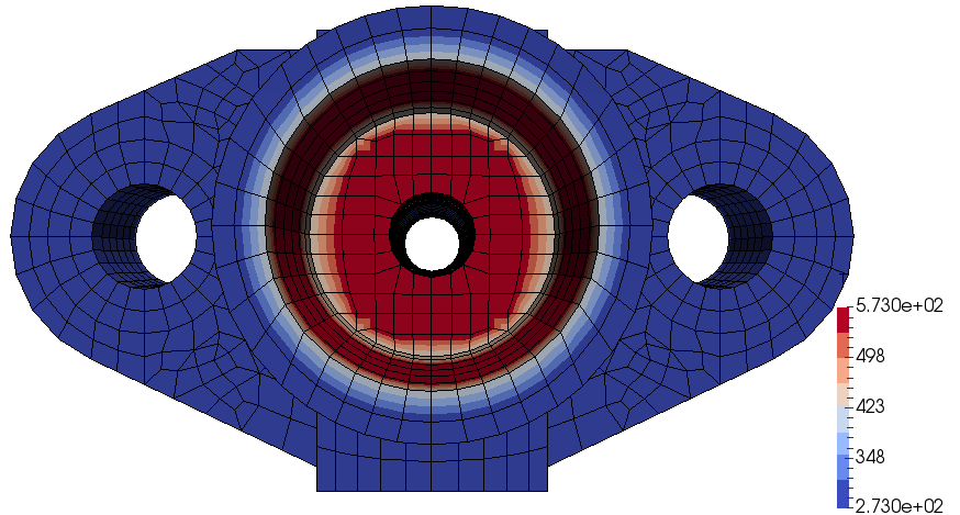
laplacianFoam/flange
Go to top
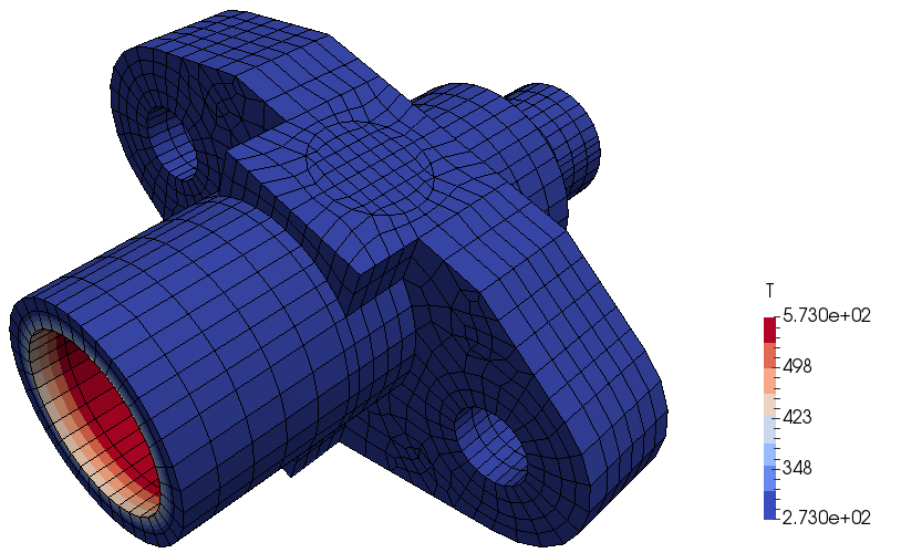
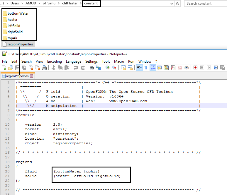
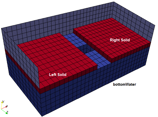
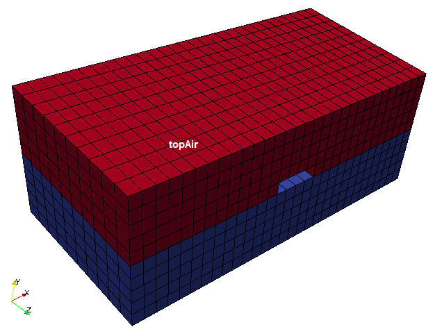
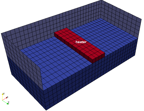
heatTransfer\chtMultiRegionFoam\multiRegionHeater
Conjugate Heat Transfer - a well documented PDF version can be found here. The tutorial section contains example of snappyHexMesh for multiple regions. A PDF version of turtorial can be found here.
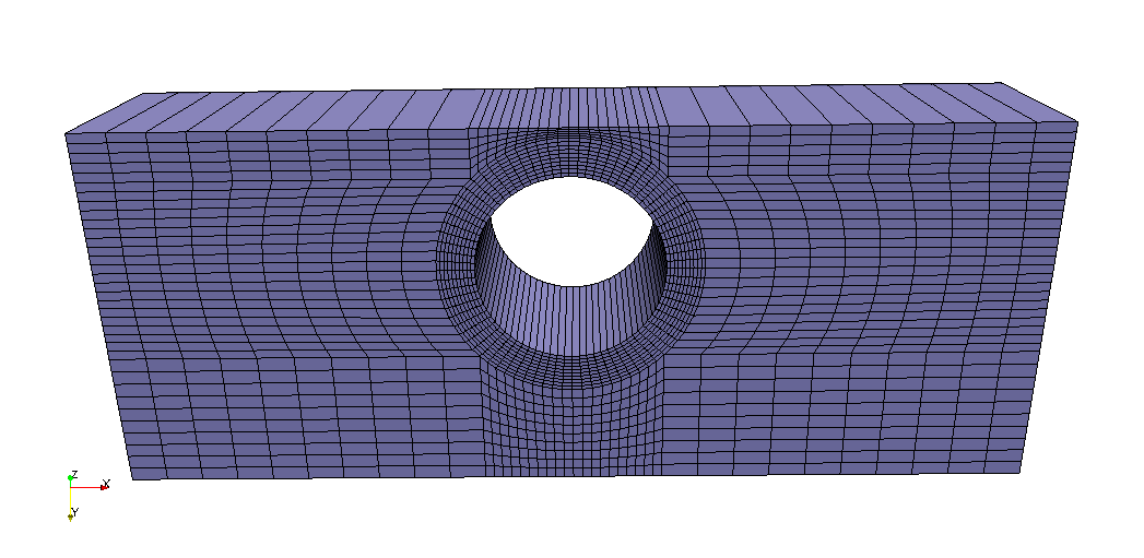
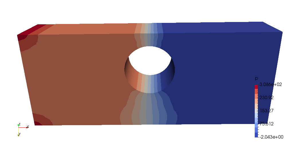
nonNewtonianIcoFoam/offsetCylinder
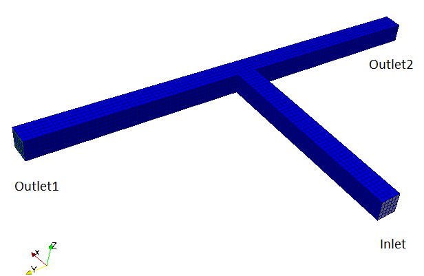
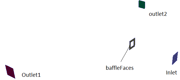
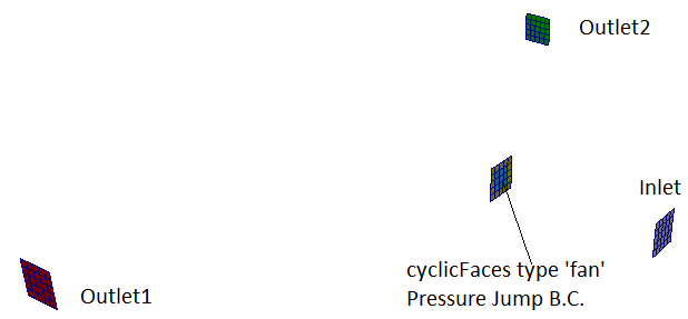
pimpleFoam This module demonstrates use of PISO-SIMPLE (PIMPLE) algorithm in test cases such as TEE-junction and fan pressure jump boundary conditions.
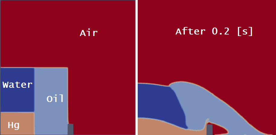
multiphase\multiphaseInterFoam\laminar\damBreak4phaseFine Multiphase flow using VOF method for 4 immiscible phases.
Electromagnetics
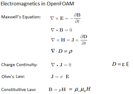
- H: magnetic field strength
- J: current density
- D: electric flux density
- E: electric field strength
- B: magnetic flux density
- μ: permeability
- σ: electrical conductivity
Adjoint Solvers: adjointShapeOptimizationFoam
Optimization of shape and size in CFD simulations require incremental change in geometry and re-meshing. The CFD programs are now incroporating adjoint solvers which runs in addition to the fuid solver to find an optimum geometry to minimize (e.g. pressure drop) or maximize (e.g. flow uniformity) specified field variables. Both the Single Object Optimization (SOO) and Multiple Objectives Optimization are possible.Similar concepts Full Order Modeling (FOM) and Reduced Order Modeling (ROM) which are based on mathematical concepts such as Higher Dimension Model (HDM), Proper Orthogonal Decomposition (POD) or Singular Value Decomposition (SVD).
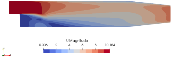
Excerpts from "Topology Optimisation of Fluids Through the Continuous Adjoint Approach in OpenFOAM" by Prof. Hakan Nilsson - "The Topology Optimization Method (TOM) consists in determine the material distribution in a design domain to maximize or minimize an objective function subject to certain constraints. To maximize/minimize the objective function at flow devices is done by adding the velocity field u multiplied by a scalar field α to the momentum equations, so regions with a high value of α determine a low permeability area (solid portion) and regions with a low value of α determine a high permeability area (fluid portion)."
For incompressible steady state Navier-Stokes equations, the problem can be written as:minimize cost function J = J(U, p, α)
such that (U . ∇)U + ∇p − ∇.[2μD(U)] + αU = 0, strain rate tensor D(ν) = ∇U + (∇U)T
∇.U = 0
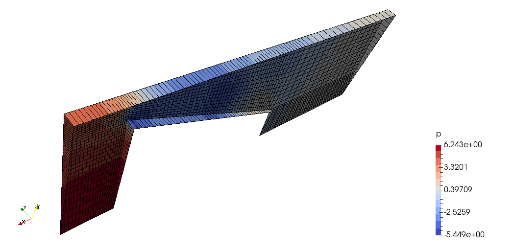
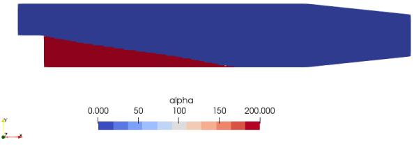
In OpenFOAM, adjointShapeOptimizationFoam solves both the primal flow (U) and the adjoint flow (Ua) and at the same time optimizes the geometry for minimized cost function say pressure loss. The solver is built around a case of optimization of a duct shape by applying blockage in regions causing pressure loss which are estimated using the adjoint method. The solver is also programmed for shape optimization with respect to pressure loss. The redundant material is shown by high value of α (closer to alphaMax specified in transportProperties dictionary. The pitzDaily case (flow over a back step with pinched outlet) gives following output:Initial Velocity
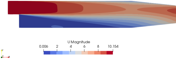
Optimized Porosity
Optimized Velocity
'Ua' and 'pa' are the adjoint velocity and the adjoint pressure. The adjointShapeOptimization solver file structure is described below.
adjointShapeOptimizationFoam
  ,--adjointOutletPressure
  |--|--adjointOutletPressureFvPatchScalarField.C
  |--|--adjointOutletPressureFvPatchScalarField.H
  |--adjointOutletVelocity
  |--|--adjointOutletVelocityFvPatchVectorField.C
  |--|--adjointOutletVelocityFvPatchVectorField.H
  |--adjointContinuityErrs.H
  |--adjointShapeOptimizationFoam.C
  |--createFields.H
  |--createPhia.H
  '--initAdjointContinuityErrs.H
- adjointContinuityErrs.H: Calculates and prints the adjoint continuity errors
- adjointShapeOptimizationFoam.C: The main solver file containing the main solver code
- createFields.H: Used to create all the fields needed for the solver
- createPhia.H: Creates and initializes the adjoint face-ux field
- initAdjointContinuityErrs.H: Declares and initializes the cumulative adjoint continuity error
The content on CFDyna.com is being constantly refined and improvised with on-the-job experience, testing, and training. Examples might be simplified to improve insight into the physics and basic understanding. Linked pages, articles, references, and examples are constantly reviewed to reduce errors, but we cannot warrant full correctness of all content.
Template by OS Templates